SHELFORD 5051
Inductor EQ / Compressor
OVERVIEW / MEDIA / FEATURES / REVIEWS / SPECS & RESOURCESClassic tone & dynamics control for the 5088.
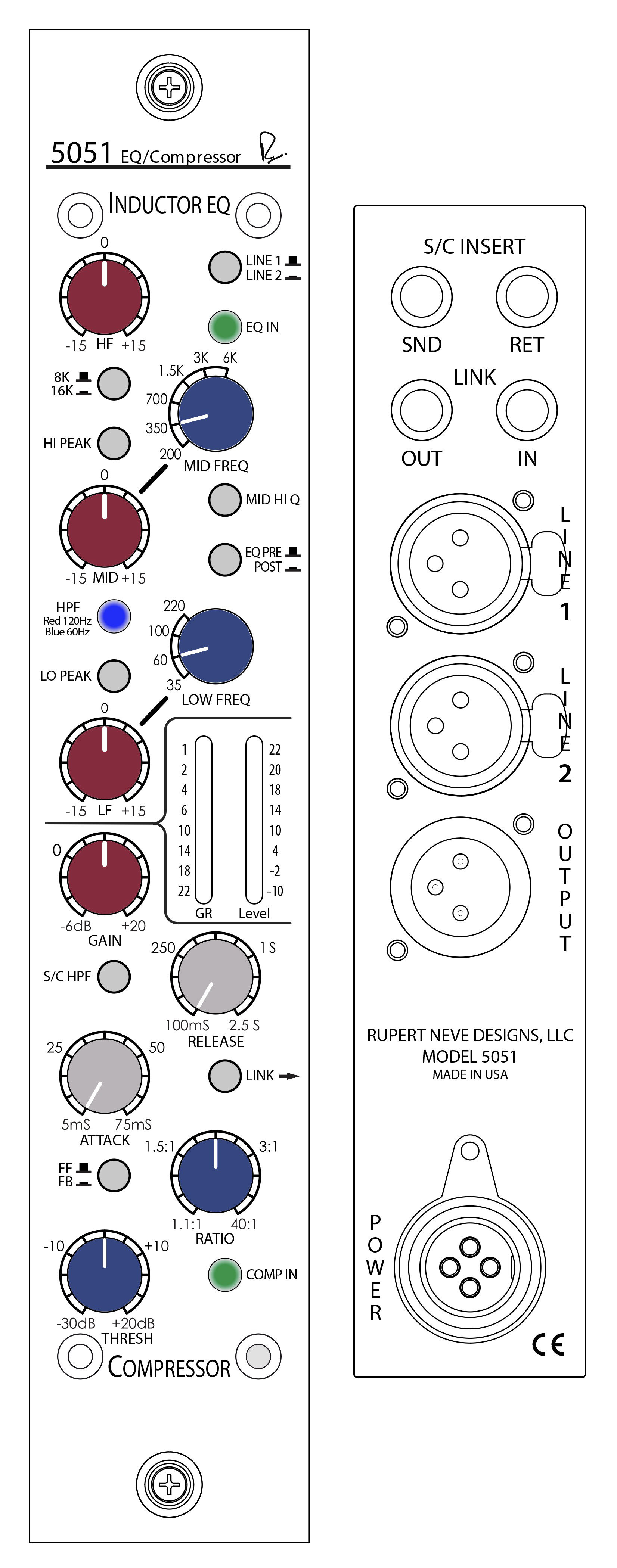
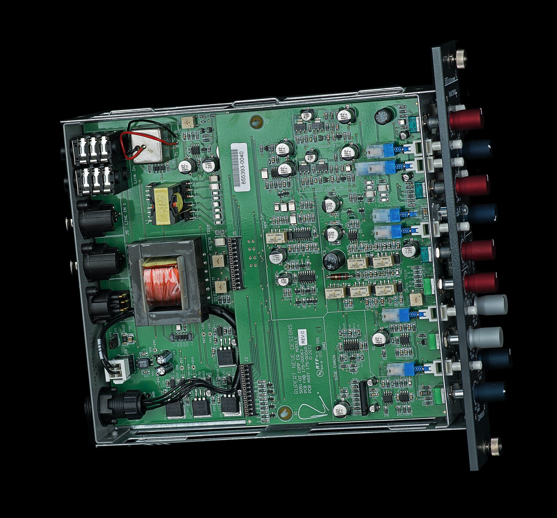
The 5051 combines a three-band Inductor EQ based on Rupert’s vintage designs with the power & flexibility of the Portico II Compressor. Utilizing a fully-discrete class-A signal path and custom audio transformers and inductors, the 5051 delivers all the performance and musicality expected from a Rupert Neve design.
“...a wonderfully flexible design capable of punchy snap compression, laid-back gluing duties and lots in between.”
What is an Inductor Equalizer?
Inductors are wires wound around a coil that provide a form of frequency-dependant resistance. When they saturate, they bring out beautifully musical harmonics that give your tracks the smooth, polished sound that has made Rupert’s consoles and equipment so desirable for over fifty years. This is what makes them different from capacitor-based EQ designs, which do a great job at surgical equalization. But inductors provide the tone.
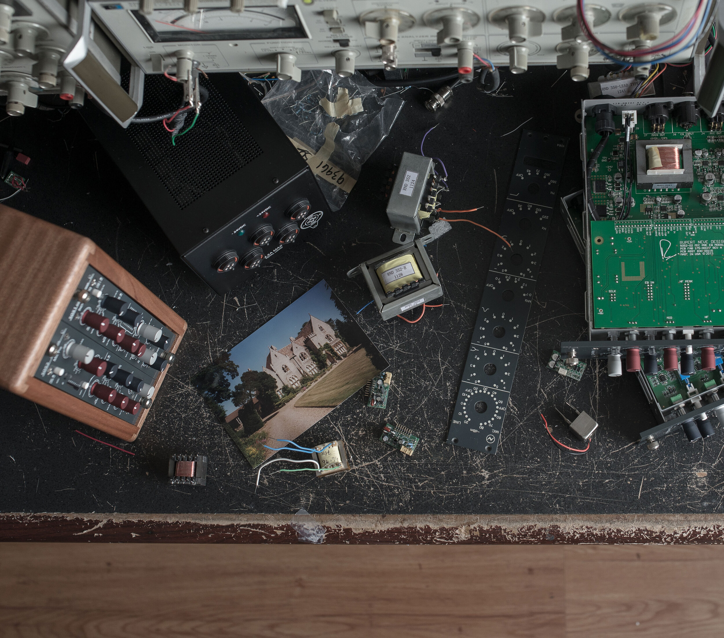
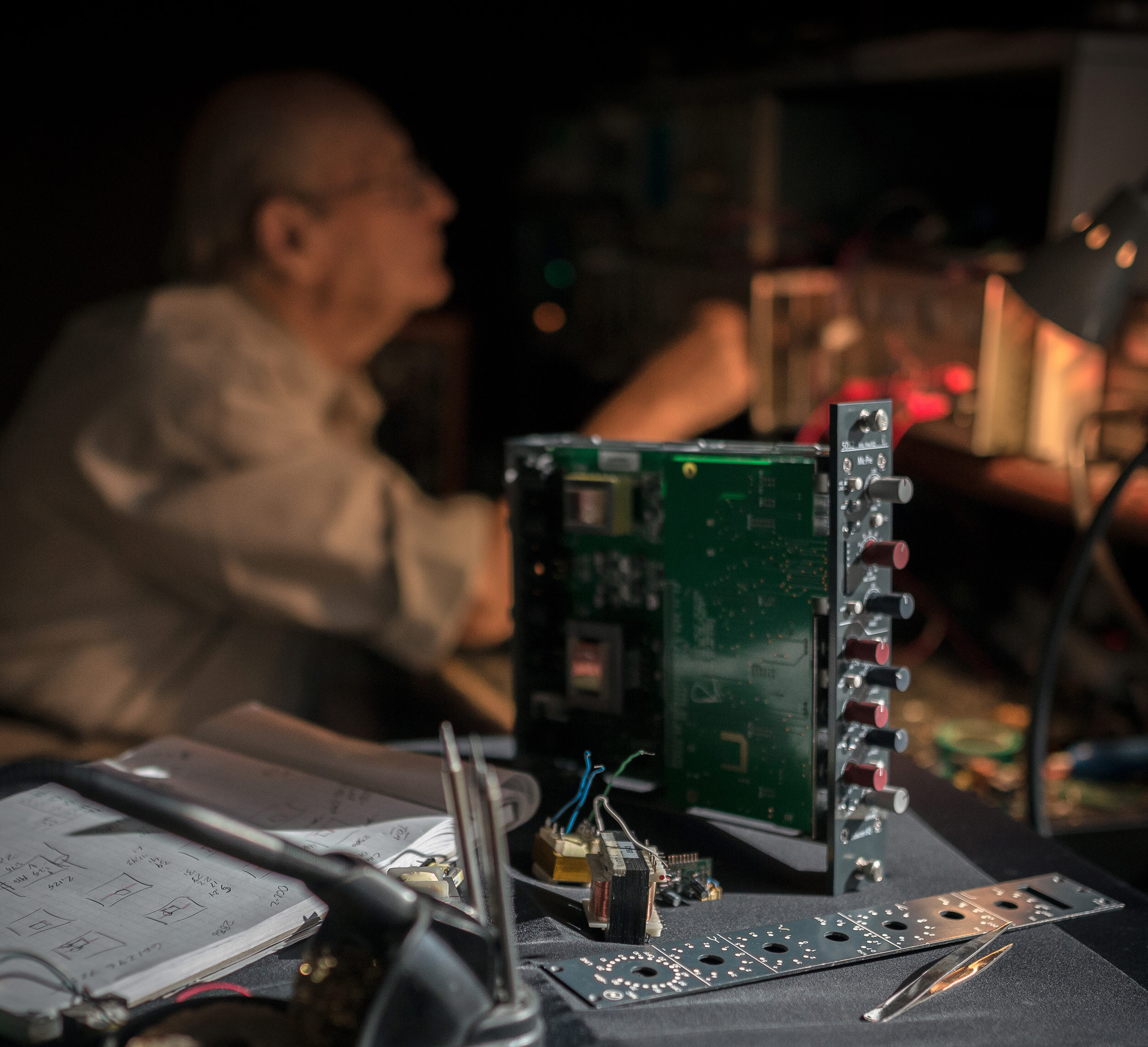
While it is certainly possible to create a functioning EQ using off-the-shelf inductors, we choose to use our own custom inductors for the 5051. This attention to detail in controlling variables such as the winding and core materials in relation to the surrounding circuitry allows the 5051 to capture the vitality and personality of Rupert’s classic designs.
The “Best-Of” EQ
The 5051’s 3-band, custom-tapped inductor EQ was inspired by our favorite elements of Rupert’s vintage EQ designs. The low frequency band is designed to produce a creamy, resonant bass response similar to a vintage 1064 – but unlike the vintage modules, the LF band on the 5051 can be used as either a shelf or a peak filter, adding punch, dimension, and control to your low end.
The midrange band is based on that of the 1073, ideal for sweetening vocals and instruments while bringing them forward in a mix, and its proportional “Q” response makes it well-suited for minimizing problematic frequencies. The high frequency band is a hybrid vintage / modern design, blending inductor circuitry with capacitor-based topologies to achieve vintage tones with enhanced control. The High Pass filter is an 18dB/octave design with a switchable 60Hz or 120Hz corner frequency, and can be used in tandem with the low frequency EQ to add low-end presence without clouding the source material.
As with Rupert’s most prized classic designs, each EQ section uses low-feedback, class-A discrete electronics to prevent low-level artifacts and harshness from detracting from the tonal shaping. However, this new circuit is a decidedly modern design with updated techniques and components that were simply not available 50 years ago, and is definitely not a “clone”.
The VCA Compressor
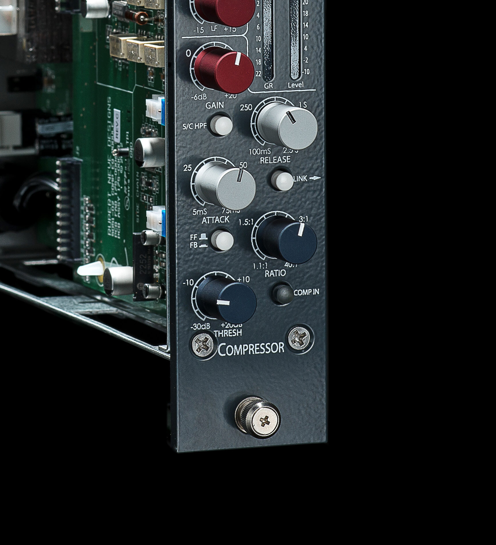
Every compressor has a gain control element in its circuit, and this is generally what determines the “sound” of the compressor. Some compressors use tubes, some use FETs, some use light-dependent resistors, some use a diode bridge – but in the 5051, a VCA (Voltage Controlled Amplifier / Attenuator) is used to control the signal’s gain.
In contrast to a diode bridge design like our 5254, which adds a thick, colorful tonality to the source, the 5051 makes use of a very accurate, low noise, low distortion VCA with essentially no sonic signature of its own. This provides an immense amount of dynamic control without leaving a heavy sonic imprint on your tracks or mixes – perfect for control across an entire console’s worth of channels.
Feed-Forward vs. Feed-Back
This switch changes the point in the signal path where the VCA control voltage is picked off: either before the VCA (feed-forward) or after the VCA (feed-back). In most of Mr. Neve’s earliest designs, feed-back detection was intrinsic to the musical dynamic response. However, the very nature of a feedback compressor limits the attack time of the compression circuit, as the control voltage has already passed through the VCA itself. To offer faster, more technically accurate response times, feed-forward detection was also implemented in the 5051: with the FF / FB switch, both classic and modern VCA responses are available.
RMS vs. Peak
One of the more unique features of our VCA compressors is the Peak / RMS mode. This switch allows the VCA to respond to both RMS (Root Mean Square) and peak levels. RMS circuits are considered to better mimic the way the ears perceive apparent loudness, while peak circuits tend to directly respond to the waveform voltage, which may be more of a concern for prevention of clipping and maximizing levels. In this case, peak mode uses a combination of both methods to get the best of both worlds, and avoids the drawbacks of each method on its own.
POWER & RACKS
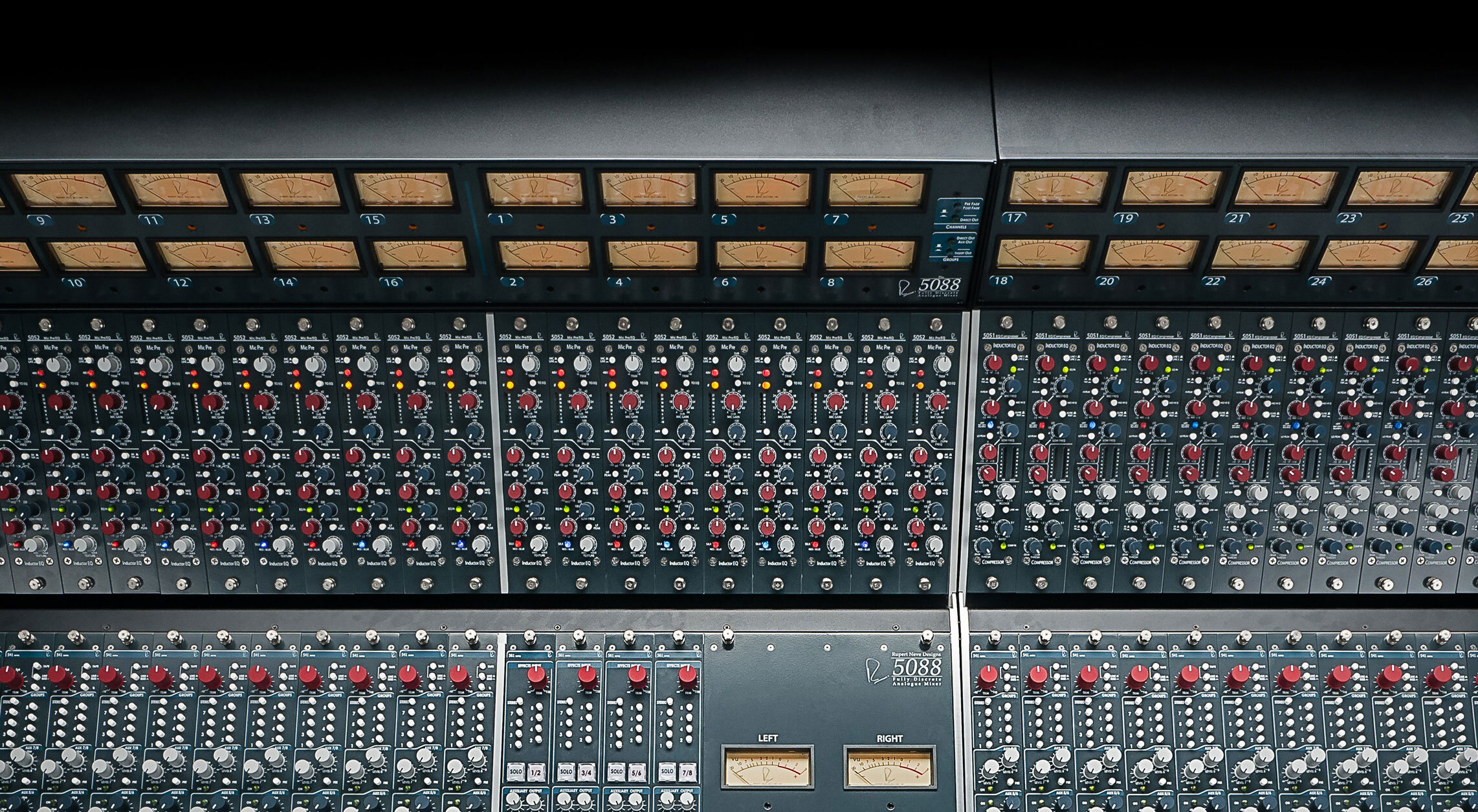
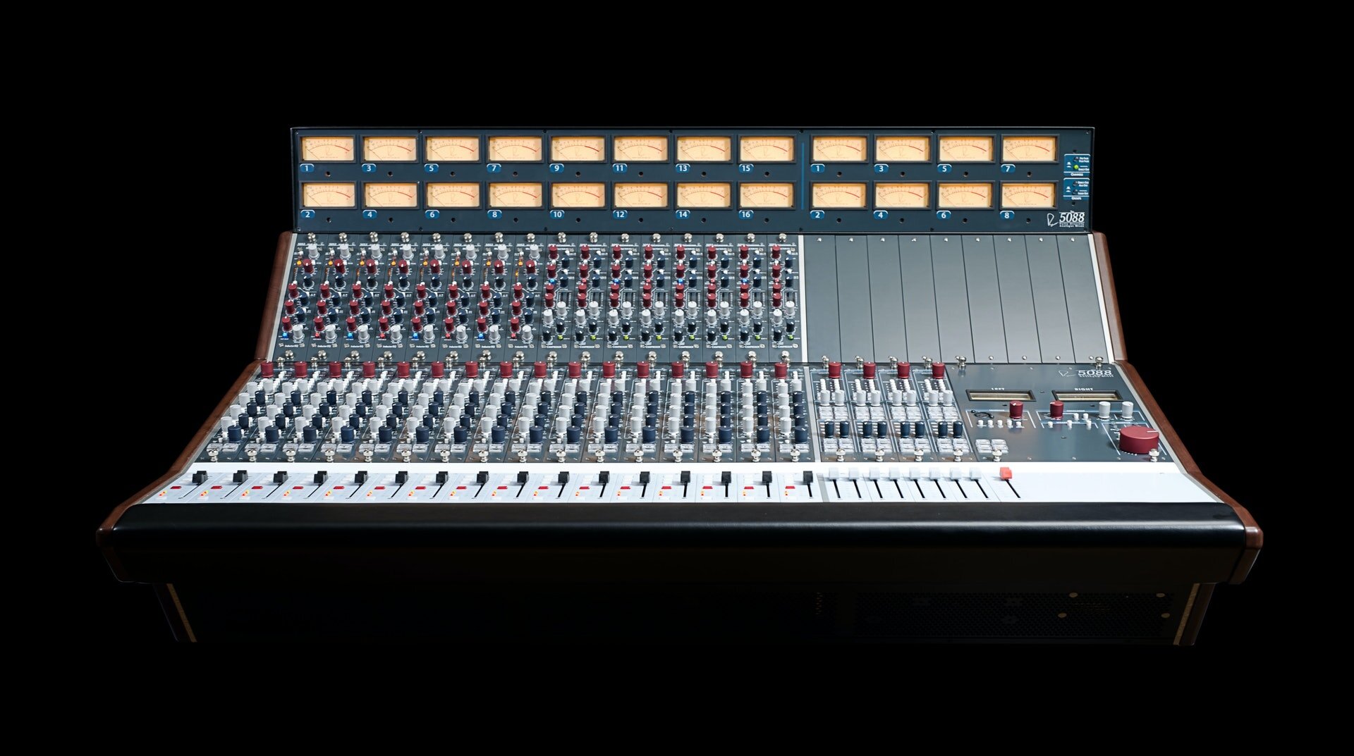
The 5051 receives +/- 24V rails from an external 25-way 2U rack-mount power supply, and can be mounted within a 5088’s penthouse section. Please see the Accessories page for more information.

HIGH FREQUENCY SHELF / PEAK
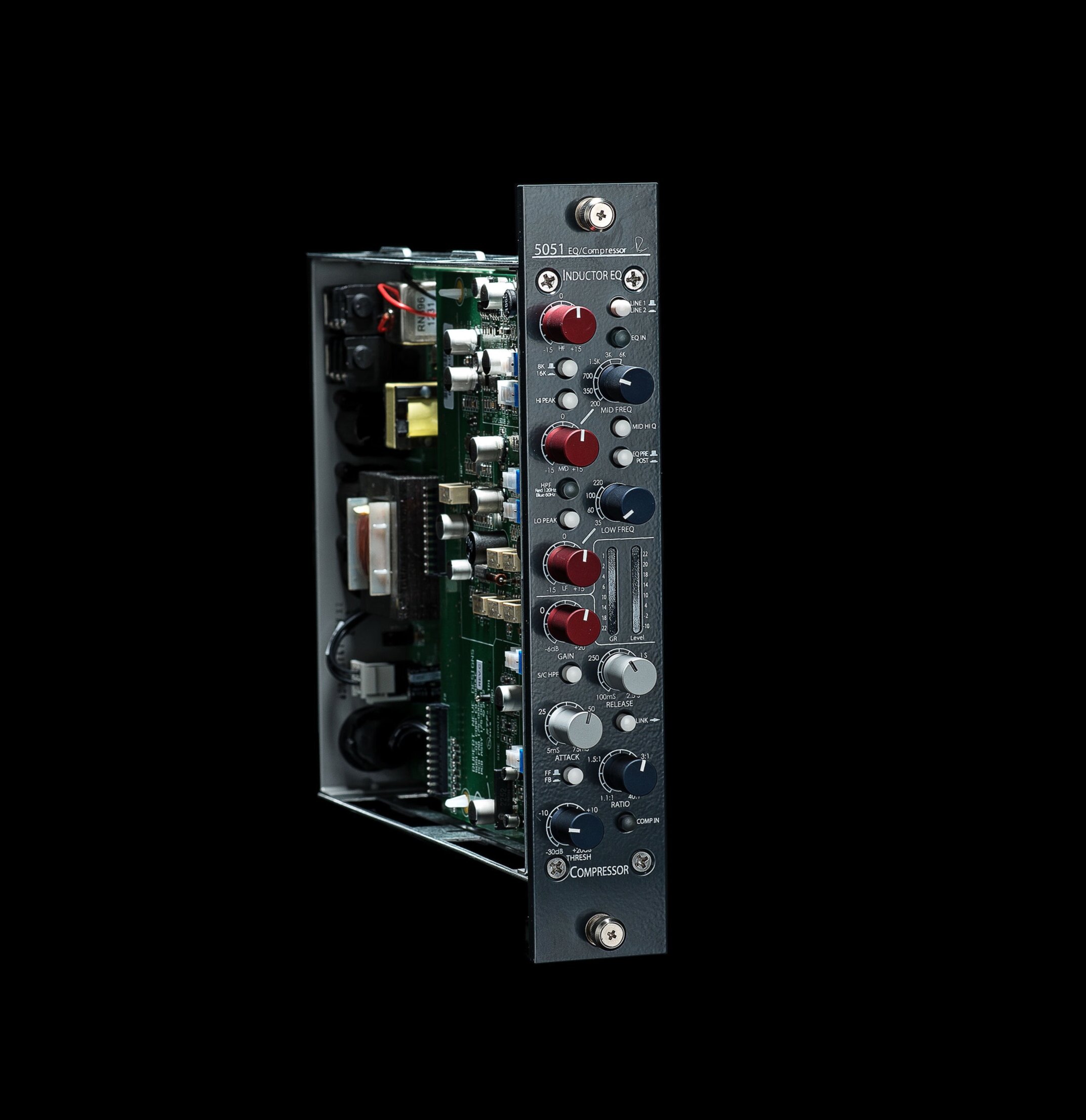
Selectable at 8 and 16kHz. With continuous gain from -15 to +15 dB. Selectable Peak or Shelf curves.
LINE SELECT
Selects been Line 1 and Line 2 inputs.
MID PARAMETRIC
Selectable at 200, 350, 700, 1.5K, 3K, and 6kHz. With continuous gain from -15 to +15 dB. Selectable Hi Q.
EQ PRE / POST
When engaged, moves the EQ after the compressor.
HPF
Cycles between bypassed, HPF at 60Hz, and HPF at 120Hz.
LOW FREQUENCY EQ
Selectable at 30, 60, 100, and 220Hz. Continuous gain from -15 to +15 dB. Selectable Peak or Shelf curves.
LEVEL & GAIN REDUCTION METERS
8-segment LED meters for monitoring Gain Reduction and Output Level.
MAKE-UP GAIN
Applies post-compressor make-up gain.
RELEASE TIME
Changes the time taken for the gain to return to 0 after the compressor disengages.
SC HPF
Applies a high-pass filter at 250Hz to the VCA side chain signal.
LINK
Links the 5051 VCA to a 2nd 5051 module, if connected.
ATTACK TIME
Changes the time delay before compression begins.
RATIO
Changes the amount of gain reduction above the set threshold level.
FF/FB
When engaged, changes the VCA detection from feed-forward to feed-back.
COMP IN
Engages the Compressor.
THRESHOLD
Sets the level at which compression begins.
REVIEWS
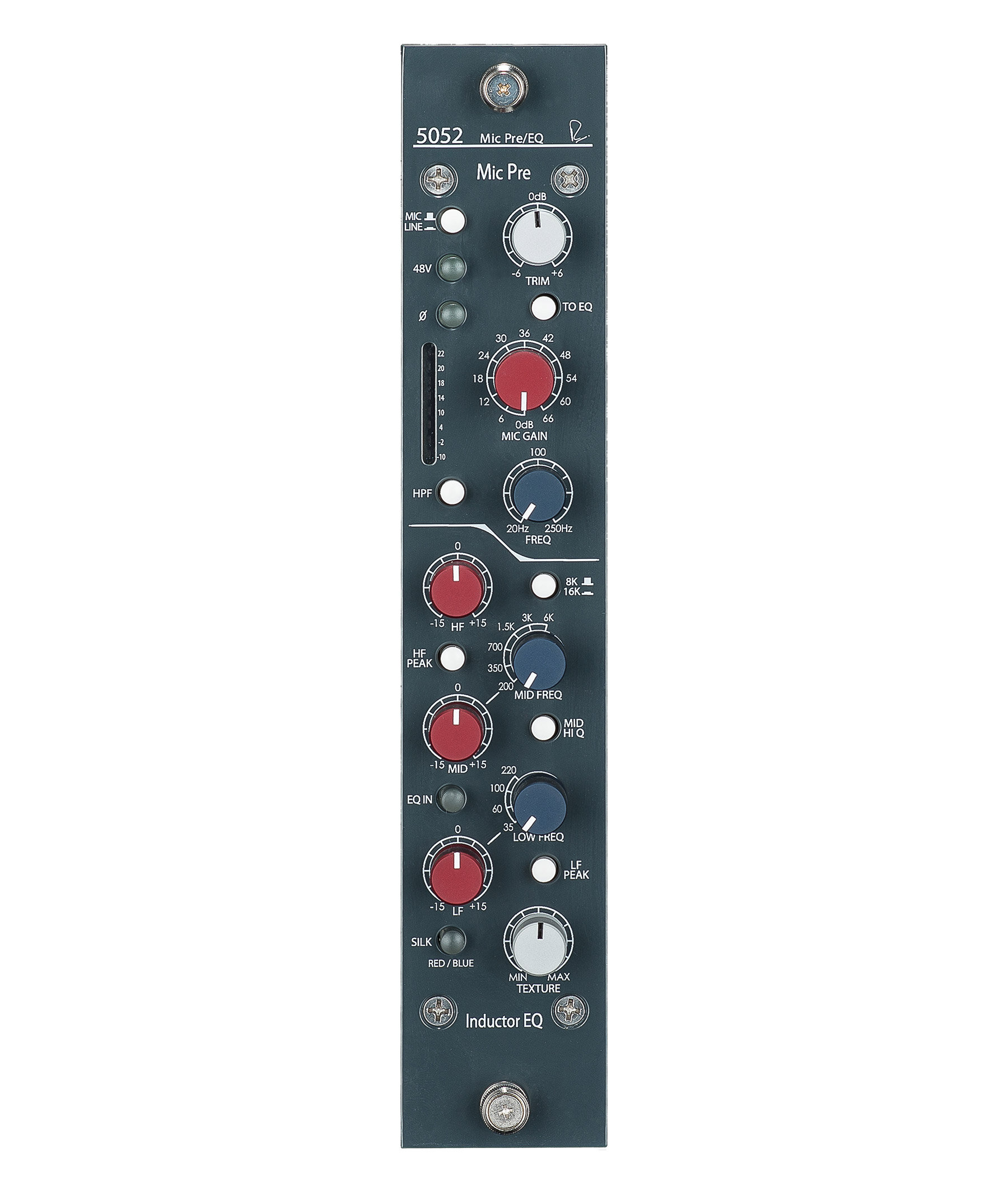
“The Rupert Neve Designs 5051 and 5052 are two of the most artistically inspiring pieces of audio gear that I’ve heard in many a year. The nature of the sound that they produce takes me right back to my early experience on 1970s Neve consoles but adds a little something that I don’t remember from back then. Everything that contributes to the classic sound of a Neve console is in there — transformers, Class–A circuitry, inductors — and, to my ears, a modern layer of detail has been added that illuminates proceedings.”
“...a wonderfully flexible design capable of punchy snap compression, laid-back gluing duties and lots in between.”
“The Shelford Series modules pay homage to the past works of Rupert Neve without exactly recreating any of them. It’s encouraging to see the company continuing to develop and design when it would be so easy to rest on the laurels of past successes. The two Shelford Series modules easily stand up as two of the best works yet created by Rupert Neve and would be welcomed into any studio around the world.”

SPECIFICATIONS & DOWNLOADS
LINE IN
FREQUENCY RESPONSE
Main Output, no load.
-3 dB @ 2.5 Hz
-3 dB @ 125 kHz
NOISE
Measured at Main Output, unweighted, 22 Hz - 22 kHz.
Terminated 40 Ohm, With gain at unity: better than -102 dBu
MAXIMUM INPUT
20 Hz to 20 kHz: +25 dBu
MAXIMUM OUTPUT
20 Hz to 20 kHz: +25 dBu
TOTAL HARMONIC DISTORTION AND NOISE
From <10 Hz to 80 kHz.
@ 1kHz, +20 dBu output: Better than 0.002%
@ 20Hz, +20 dBu out: Better than 0.120%
@ 20kHz, +20 dBu out: Better than 0.010%
EQUALIZER
NOISE
Measured at Main Output, unweighted, 22 Hz-22 kHz. Terminated 40 Ohm with all gains set at 0.
Better than -92 dBu
MAXIMUM INPUT
20 Hz to 20 kH: +24.5 dBu
MAXIMUM OUTPUT
20 Hz to 20 kHz: +24.5 dBu
TOTAL HARMONIC DISTORTION AND NOISE
From <10 Hz to 80 kHz.
@ 1kHz, +20 dBu output: Better than 0.007%
@ 20Hz, +20 dBu out: Better than 0.120%
@ 20kHz, +20 dBu out: Better than 0.070%
COMPRESSOR (Threshold at +20 dB, Ratio at 1.1:1, Gain at 0.)
NOISE
Measured at Main Output, unweighted, 22Hz - 22kHz. Terminated 40 Ohm.
Better than -92 dBu
MAXIMUM INPUT
20 Hz to 20 kHz: +25 dBu
MAXIMUM OUTPUT
20 Hz to 20 kHz: +25 dBu
TOTAL HARMONIC DISTORTION AND NOISE
From <10 Hz to 80 kHz.
@ 1 kHz, +20 dBu output: Better than 0.020%
@ 20 Hz, +20 dBu output: Better than 0.140%
@ 20 kHz, +20 dBu output: Better than 0.070%
THRESHOLD
Continuously Variable from -30 dBu to +20 dBu
RATIO
Continuously Variable from 1.1:1 to 40:1
GAIN
Continuously Variable from -6 dB to +20 dB
ATTACK
Continuously Variable from 5mS to 75mS
RELEASE
Continuously Variable from 100mS to 2.5 Seconds
UNIT DIMENSIONS
1.75” W x 8.75” D x 9.4” H
(4.5 cm W x 22.2 cm D x 23.9 cm H)
UNIT WEIGHT
3.5 lbs. (1.6 kg)
SHIPPING DIMENSIONS
14” W x 14” D x 7” H
(35.6 cm W x 35.6 cm D x 17.8 cm H)
SHIPPING WEIGHT
6 lbs. (2.7 kg)
FREQUENTLY ASKED QUESTIONS
The 5051 uses essentially the same inductor EQ design, but some of the surrounding circuitry is different.
The 5051 has a very similar compressor to the Master Buss Processor. The primary difference is in the overall feature set.
Though a diode bridge compressor design like the one in our Shelford Channel, 5254 or 535 compressors has a thicker, more “vintage” quality to it, it’s not necessarily appropriate for every channel on a console. The VCA compressor used in the 5051 can be very smooth and unobtrusive, and is an ideal “general purpose” compressor for simultaneous use across many channels in a mix.
Yes, this is normal. When the frequency positions are changed, the switch momentarily breaks the connection in the audio path, which can cause a click. (Note: how much of a click or pop you hear may also be dependent on the source material, as well as the amount of boosting you’re doing with the control). On the LF band, you may also hear a slight mechanical click from inside the unit itself. That’s the sound of relays switching to change the frequency selection.


